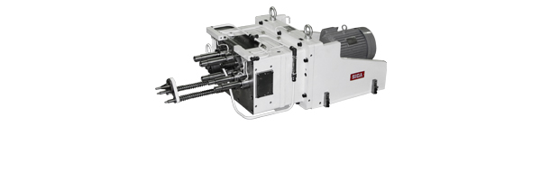
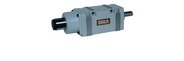
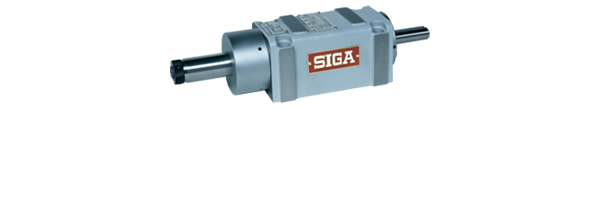
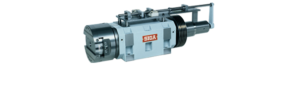
Spindle Unit
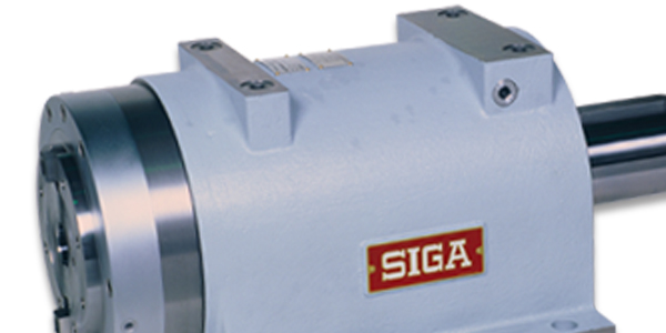
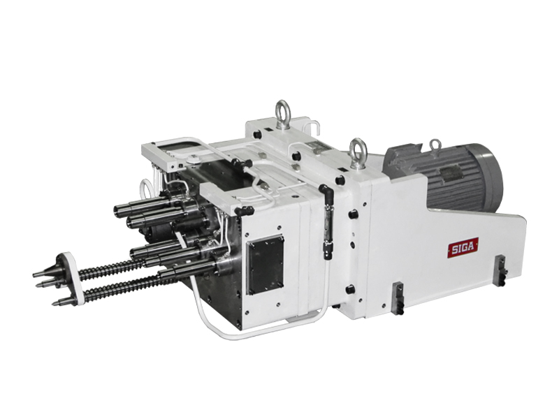
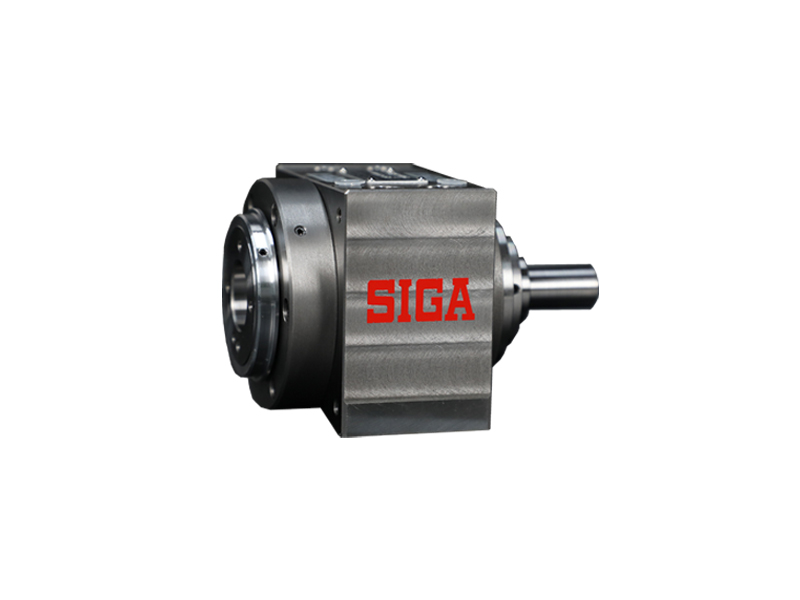
The SIGA Spindle Unit has been on sale since 1960 and has been adopted in major production sites both domestically and overseas for many years.
Our rich lineup established by that know-how is highly valued for its durability and short delivery time, and we still have many customers who specify "The spindle is SIGA" when creating new dedicated machine tools.
If the unit you request is not in the lineup, we also support the production of special items from one unit.
We also support bearing replacement and overhauls, so you can use it for a long time.
7F
7F-50
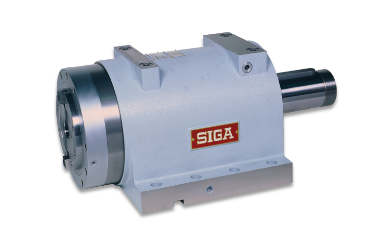
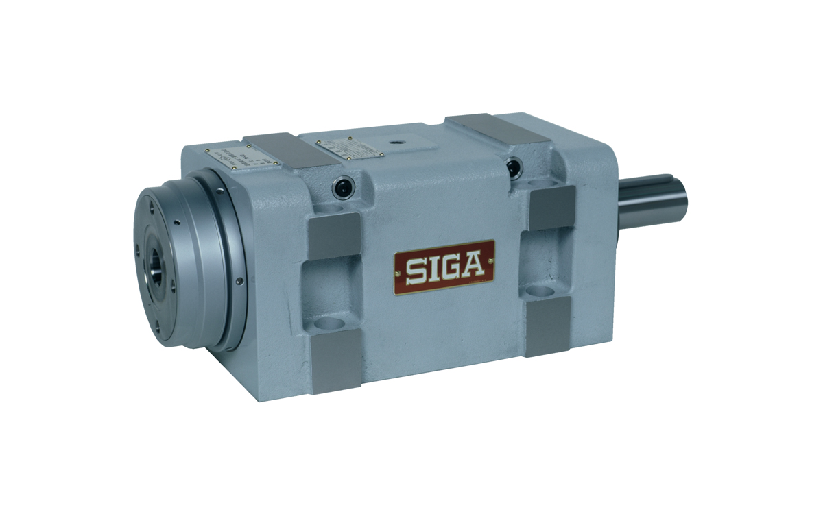
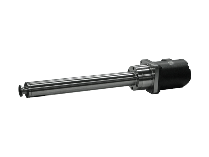
It is mainly intended for high-precision, light-load, high-speed cutting and finish boring.
Angular ball bearings are used. The lineup of spindle diameters ranges from φ20 to φ60.
The 4F-G type gundrill spindle has the same structure.
| Spindle Diameter | Motor Output | Case K Compatible | Case P Compatible |
| 20-60mm | 0.75KW-3.7KW | 〇 | ✕ |
Check 7F details
| Type | Spindle Diameter (mm) |
Usual Maximum Rotation Speed (rpm) |
Maximum Permissible Motor Power (KW) |
Used Bearings | Weight (Kgf) |
CAD Data |
|
| 7F-20 | 20 | 10,000 | 0.75 | Angular Ball Bearings |
9.7 | zip / lzh | |
| 7F-30 | 30 | 4,500 | 2.2 | 26 | zip / lzh | ||
| 7F-30-K | 30 | 4,500 | 2.2 | 26 | zip / lzh | ||
| 7F-40 | 40 | 3,800 | 2.2 | 36 | zip / lzh | ||
| 7F-40-K | 40 | 3,800 | 2.2 | 35 | zip / lzh | ||
| 7F-45 | 45 | 3,500 | 2.2 | 37.5 | zip / lzh | ||
| 7F-45-K | 45 | 3,500 | 2.2 | 36.5 | zip / lzh | ||
| 7F-50 | 50 | 3,000 | 3.7 | 63 | zip / lzh | ||
| 7F-50-K | 50 | 3,000 | 3.7 | 63 | zip / lzh | ||
| 7F-60 | 60 | 2,500 | 3.7 | 83 | zip / lzh | ||
| 7F-60-K | 60 | 2,500 | 3.7 | 80 | zip / lzh | ||
6F
6F-60
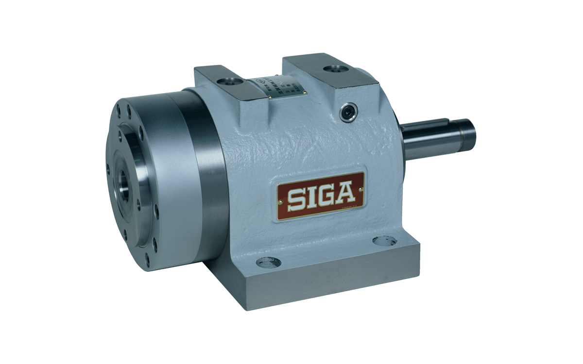
It is mainly designed for high-speed, high-precision, and medium-load finish boring.
Using 7000 series angular ball bearings and NN30K series double-row cylindrical roller bearings, it enables high-speed rotation beyond conventional micro fog lubrication with grease lubrication.
Spindle diameter lineup is from φ40 to φ100.
| Spindle diameter | Motor output | Case K Compatible | Case P Compatible |
| 40―130mm | 2.2―22KW | ― | ― |
Check 6F details
| Type | Spindle diameter (mm) |
Common maximum rotation speed (rpm) |
Maximum permissible motor power (KW) |
Used bearings | Weight (Kgf) |
CAD Data |
|
| 6F-40 | 40 | 7,000 | 2.2 | Angular Ball bearings + Double-row cylindrical roller bearings |
48 | zip / lzh | |
| 6F-50 | 50 | 6,000 | 3.7 | 49 | zip / lzh | ||
| 6F-60 | 60 | 5,000 | 3.7 | 77 | zip / lzh | ||
| 6F-75 | 75 | 4,000 | 5.5 | 130 | zip / lzh | ||
| 6F-85 | 85 | 3,500 | 7.5 | 165 | zip / lzh | ||
| 6F-100 | 100 | 3,000 | 15 | 231 | zip / lzh | ||
| 6F-120 | 120 | 2,500 | 18.5 | 340 | zip / lzh | ||
| 6F-130 | 130 | 2,200 | 22 | 410 | zip / lzh | ||
8F
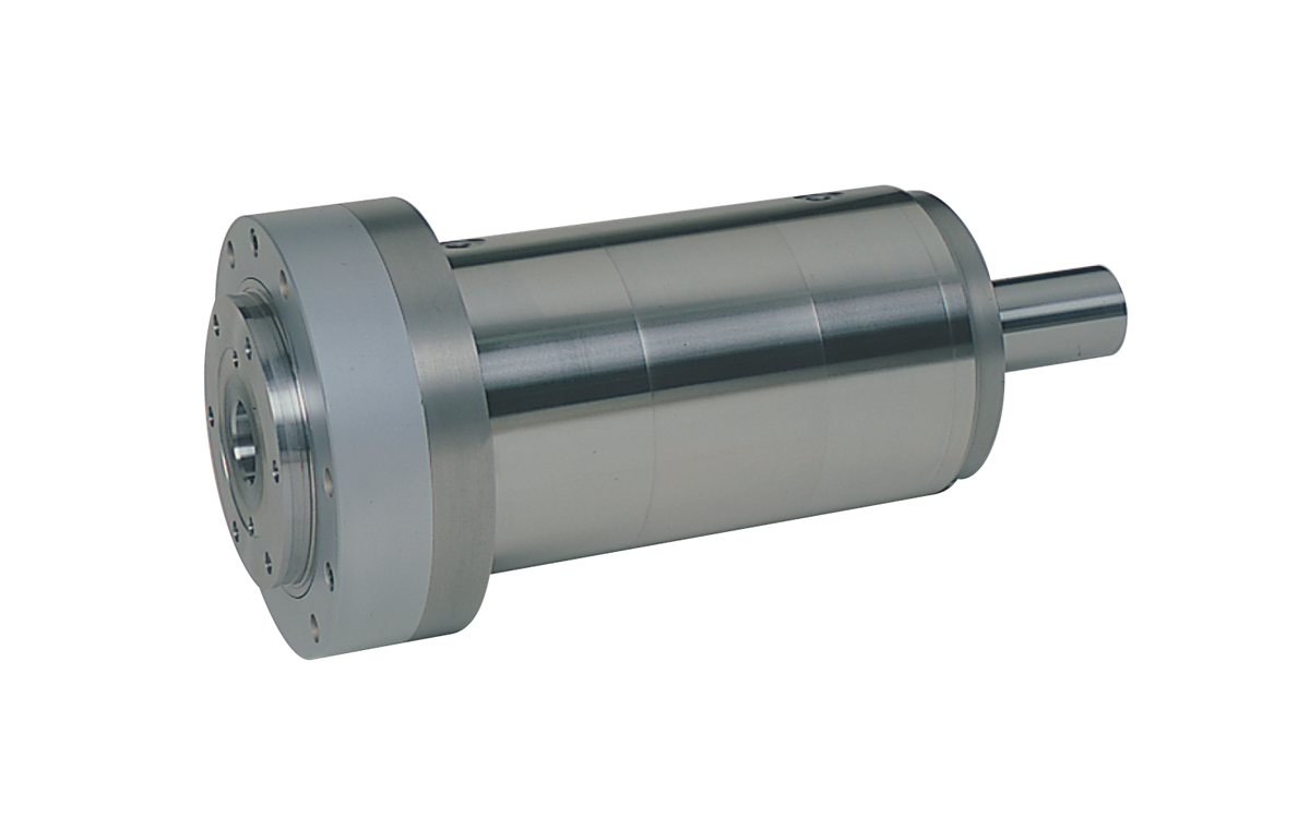
8Fquill
It is suitable for machining that requires higher speed than 6F type and 7F type, and equivalent or higher accuracy, using 7000 series angular ball bearings.
The spindle diameter lineup is from φ40 to φ100.
The spindle case is the same as the 6F type.
| Spindle diameter | Motor output | Case K Compatible | Case P Compatible |
| 40―120mm | 2.2―18.5KW | ー | ー |
Check 8F details
| Type | Spindle diameter (mm) |
Common maximum rotation speed (rpm) |
Maximum permissible motor power (KW) |
Used bearings | Weight (Kgf) |
CAD Data |
|
| 8F-40 | 40 | 10,000 | 2.2 | Angular Ball bearings |
48 | zip / lzh | |
| 8F-50 | 50 | 8,000 | 3.7 | 49 | zip / lzh | ||
| 8F-60 | 60 | 6,700 | 3.7 | 77 | zip / lzh | ||
| 8F-75 | 75 | 5,400 | 5.5 | 130 | zip / lzh | ||
| 8F-85 | 85 | 4,700 | 7.5 | 165 | zip / lzh | ||
| 8F-100 | 100 | 4,000 | 15 | 231 | zip / lzh | ||
| 8F-120 | 120 | 3,000 | 18.5 | 340 | zip / lzh | ||
4F
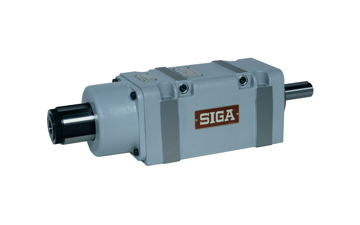
4F-45G
Based on the 7F type boring spindle, it is mainly intended for gundrill machining.
An inducer (rotational joint) is attached to the pulley shaft end to support coolant-through.
It comes standard with a drip-proof cover to prevent cutting oil from entering the interior. Air purge is essential.
The dedicated gundrill holder and socket are sold separately.
| Spindle diameter | Motor output | Case K Compatible | Case P Compatible |
| 30―60mm | 2.2―3.7KW | ー | ー |
Check 4F details
| Type | Spindle diameter (mm) |
Common maximum rotation speed (rpm) |
Maximum permissible motor power (KW) |
Used bearings | Weight (Kgf) |
CAD Data |
|
| 4F-30G | 30 | 5,000 | 2.2 | Angular Ball Bearing |
26 | zip / lzh | |
| 4F-30G-K | 30 | 5,000 | 2.2 | 26 | zip / lzh | ||
| 4F-40G | 40 | 4,000 | 2.2 | 36 | zip / lzh | ||
| 4F-40G-K | 40 | 4,000 | 2.2 | 35 | zip / lzh | ||
| 4F-45G | 45 | 3,500 | 2.2 | 37.5 | zip / lzh | ||
| 4F-45G-K | 45 | 3,500 | 2.2 | 36.5 | zip / lzh | ||
| 4F-50G | 50 | 3,000 | 3.7 | 63 | zip / lzh | ||
| 4F-50G-K | 50 | 3,000 | 3.7 | 63 | zip / lzh | ||
| 4F-60G | 60 | 2,500 | 3.7 | 83 | zip / lzh | ||
| 4F-60G-K | 60 | 2,500 | 3.7 | 80 | zip / lzh | ||
3R
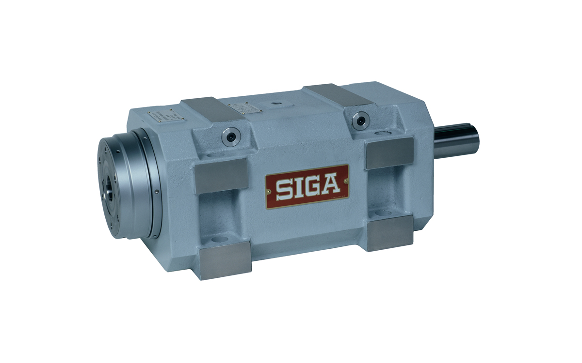
3R-70
It is mainly intended for heavy-duty boring and milling operations.
It consists of two tapered rollers and two angular ball bearings (or one cylindrical roller bearing), making it a fully three-point supported configuration.
The spindle diameter lineup ranges from φ25 to φ120. Sizes 3R-25-AP and 3R-75-AP and above are of the straight boring type.
※ A straight boring type is a type that does not have a quill and directly incorporates bearings into the cast iron case.
| Spindle Diameter | Motor Output | Case K Compatible | Case P Compatible |
| 25―120mm | 1.5―18.5KW | 〇 | ✕ |
Check 3R Details
| Model | Spindle Diameter (mm) |
Maximum Usual Rotation Speed (rpm) |
Maximum Allowable Motor Power (KW) |
Bearing Used | Weight (Kgf) |
CAD Data |
|
| 3R-25 | 25 | 3,800 | 1.5 | Tapered Roller Bearing + Angular Ball Bearing |
9.7 | zip / lzh | |
| 3R-30 | 30 | 3,000 | 2.2 | 26 | zip / lzh | ||
| 3R-30-K | 30 | 3,000 | 2.2 | 26 | zip / lzh | ||
| 3R-40 | 40 | 2,700 | 2.2 | 36 | zip / lzh | ||
| 3R-40-K | 40 | 2,700 | 2.2 | 35 | zip / lzh | ||
| 3R-45 | 45 | 2,500 | 2.2 | 37.5 | zip / lzh | ||
| 3R-45-K | 45 | 2,500 | 2.2 | 36.5 | zip / lzh | ||
| 3R-50 | 50 | 2,000 | 3.7 | 63 | zip / lzh | ||
| 3R-50-K | 50 | 2,000 | 3.7 | 63 | zip / lzh | ||
| 3R-60 | 60 | 1,500 | 3.7 | 83 | zip / lzh | ||
| 3R-60-K | 60 | 1,500 | 3.7 | 80 | zip / lzh | ||
| 3R-75 | 75 | 1,000 | 5.5 | Tapered roller bearings + Cylindrical roller bearings |
115 | zip / lzh | |
| 3R-75-K | 75 | 1,000 | 5.5 | 115 | zip / lzh | ||
| 3R-85 | 85 | 900 | 7.5 | 145 | zip / lzh | ||
| 3R-85-K | 85 | 900 | 7.5 | 137 | zip / lzh | ||
| 3R-100 | 100 | 700 | 15 | 233 | zip / lzh | ||
| 3R-120 | 120 | 500 | 18.5 | 380 | zip / lzh | ||
4R
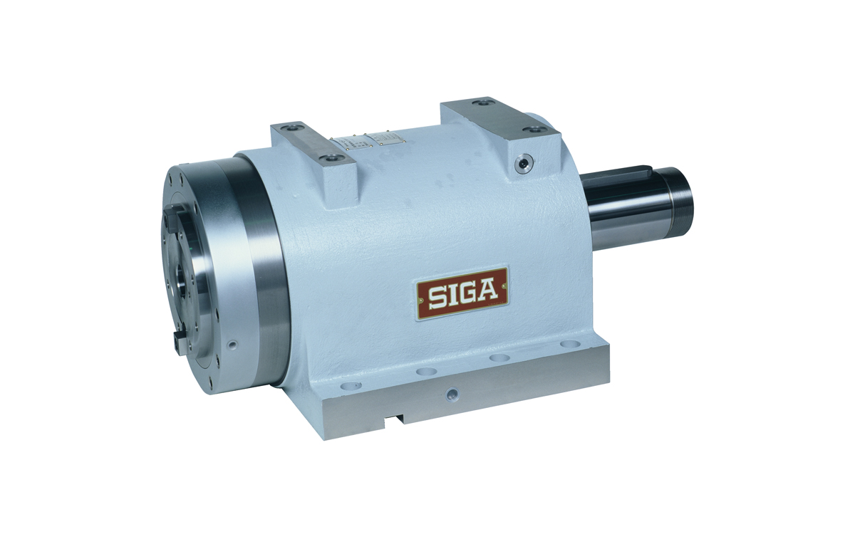
4R-130
By using double row cylindrical roller bearings and double row thrust angular ball bearings, we achieve high rotation accuracy, high-speed rotation, high rigidity, and low temperature rise with grease lubrication.
It can be used for a wide range from rough boring to finish boring.
The spindle diameter lineup ranges from φ40 to φ130.
| Spindle Diameter | Motor Output | Case K Compatible | Case P Compatible |
| 40―130mm | 2.2―22KW | ✕ | ✕ |
Check 4R Details
| Model | Spindle Diameter (mm) |
Maximum Usual Rotation Speed (rpm) |
Maximum Allowable Motor Power (KW) |
Bearing Used | Weight (Kgf) |
CAD Data |
|
| 4R-40 | 40 | 4,500 | 2.2 | Double Row Cylindrical Roller Bearing + Double Row Thrust Angular Ball Bearing |
48 | zip / lzh | |
| 4R-50 | 50 | 4,000 | 3.7 | 49 | zip / lzh | ||
| 4R-60 | 60 | 3,400 | 3.7 | 77 | zip / lzh | ||
| 4R-75 | 75 | 2,800 | 5.5 | 130 | zip / lzh | ||
| 4R-85 | 85 | 2,500 | 7.5 | 165 | zip / lzh | ||
| 4R-100 | 100 | 2,200 | 15 | 231 | zip / lzh | ||
| 4R-120 | 120 | 1,800 | 18.5 | 340 | zip / lzh | ||
| 4R-130 | 130 | 1,500 | 22 | 410 | zip / lzh | ||
FA
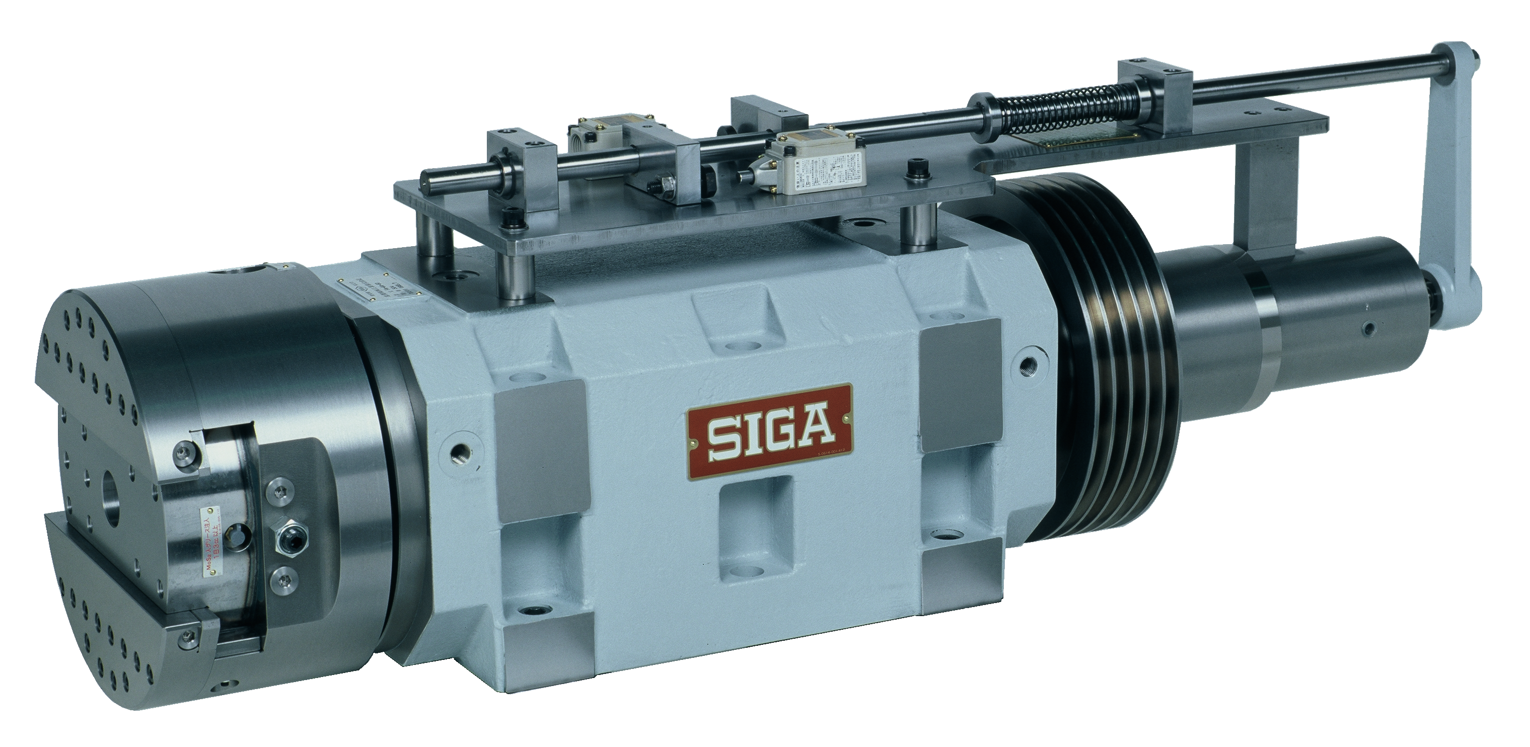
FA-6
This spindle enables facing by sliding the holder part.
Depending on the method of use, choose from each size, rack and pinion method and wedge method.
Although it is hydraulically driven as standard, we also have a wealth of production experience for ball screw drive types.
Check FA Details
| Model | Spindle Diameter (mm) |
Maximum Usual Rotation Speed (rpm) |
Maximum Allowable Motor Power (KW) |
Bearing Used | Weight (Kgf) |
CAD Data |
| FA-2H-10 | 70 | 600 | 2.2 | Tapered Roller Bearing + Angular Ball Bearing |
137 | zip / lzh |
| FA-2E-30 | 60 | 600 | 2.2 | 137 | zip / lzh | |
| FA-5C-5 | 60 | 800 | 1.5 | 110 | zip / lzh | |
| FA-4D-10 | 85 | 600 | 3.7 | Tapered Roller Bearing + Cylindrical Roller Bearing |
215 | zip / lzh |
| FA-4B-30 | 85 | 600 | 3.7 | 215 | zip / lzh | |
| FA-6C-10 | 100 | 600 | 7.5 | 360 | zip / lzh | |
| FA-6A-50 | 100 | 600 | 7.5 | 360 | zip / lzh | |
| FA-7A-10 | 120 | 500 | 7.5 | 590 | zip / lzh | |
| FA-7A-70 | 120 | 500 | 7.5 | 590 | zip / lzh |
7M
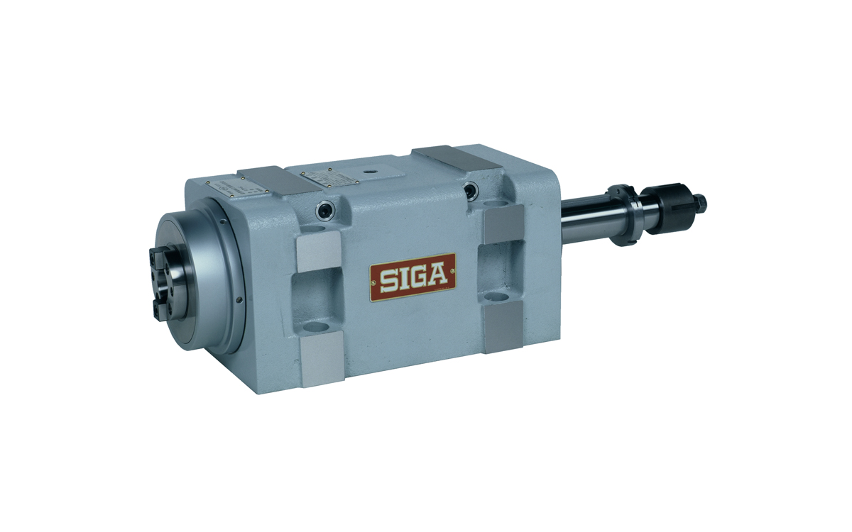
7M-50
It is designed for high-precision, light-load, high-speed milling operations.
The spindle end adopts JIS B.6101 (NT taper) 30 and 40 numbers.
The bearing configuration is the same as the 7F type boring spindle.
The shaft diameter lineup is φ50 and φ60.
| Spindle Diameter | Motor Power | Case K Compatible | Case P Compatible |
| 50―60mm | 3.7KW | 〇 | ー |
Check 7M Details
| Model | Spindle Diameter | Usual Maximum Rotation Speed (rpm) |
Maximum Allowable Motor Power (KW) |
Used Bearings | Weight (Kgf) |
CAD Data |
|
| (mm) | NT # | ||||||
| 7M-50F | 50 | 30 | 3,000 | 3.7 | Angular Ball Bearing |
66 | zip / lzh |
| 7M-50F-K | 50 | 30 | 3,000 | 3.7 | 66 | zip / lzh | |
| 7M-60F | 60 | 40 | 2,500 | 3.7 | 84 | zip / lzh | |
| 7M-60F-K | 60 | 40 | 2,500 | 3.7 | 81 | zip / lzh | |
2M
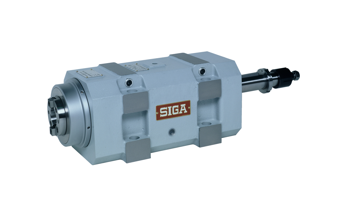
2M-60
It is designed for heavy-load milling and boring operations.
The spindle end adopts JIS B.6101 (NT taper) 30, 40, and 50 numbers.
The bearing configuration is the same as the 3R type boring spindle.
The shaft diameter lineup ranges from φ50 to φ120.
| Spindle Diameter | Motor Power | Case K Compatible | Case P Compatible |
| 50―120mm | 3.7―18.5KW | 〇 | ー |
Check 2M Details
| Model | Spindle Diameter | Usual Maximum Rotation Speed (rpm) |
Maximum Allowable Motor Power (KW) |
Used Bearings | Weight (Kgf) |
CAD Data |
|
| (mm) | NT # | ||||||
| 2M-50R | 50 | 30 | 2,000 | 3.7 | Tapered roller bearings + Angular contact ball bearings |
66 | zip / lzh |
| 2M-50R-K | 50 | 30 | 2,000 | 3.7 | 66 | zip / lzh | |
| 2M-60R | 60 | 40 | 1,500 | 3.7 | 84 | zip / lzh | |
| 2M-60R-K | 60 | 40 | 1,500 | 3.7 | 81 | zip / lzh | |
| 2M-75R | 75 | 40 | 1,000 | 5.5 | Tapered roller bearings + Cylindrical roller bearings |
115 | zip / lzh |
| 2M-75R-K | 75 | 40 | 1,000 | 5.5 | 115 | zip / lzh | |
| 2M-85R | 85 | 50 | 900 | 7.5 | 145 | zip / lzh | |
| 2M-100R | 100 | 50 | 700 | 15 | 233 | zip / lzh | |
| 2M-120R | 120 | 50 | 500 | 18.5 | 320 | zip / lzh | |
4M
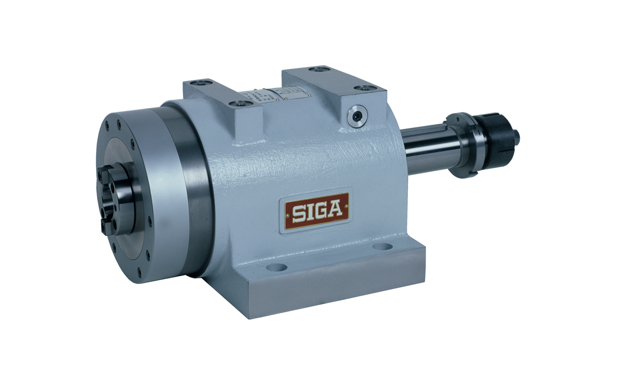
4M-75
There are two types available: 4M-F type for high-speed, high-precision, medium-load milling and boring operations, and 4M-R type for high-speed, heavy-load operations.
The spindle end adopts JIS B.6101 (NT taper) 40 and 50 numbers.
The bearing configuration is as follows:
・4M-F type is the same as the 6F boring spindle
・4M-R type is the same as the 4R boring spindle
The shaft diameter lineup ranges from φ60 to φ120.
| Spindle Diameter | Motor Power | Case K Compatible | Case P Compatible |
| 60―120mm | 3.7―18.5KW | 〇 | ✕ |
Check 4M Details
| Model | Spindle Diameter | Usual Maximum Rotation Speed (rpm) |
Maximum Allowable Motor Power (KW) |
Used Bearings | Weight (Kgf) |
CAD Data |
|
| (mm) | NT # | ||||||
| 4M-60F | 60 | 40 | 5,000 | 3.7 | Angular contact ball bearings + Double row cylindrical roller bearings |
78 | zip / lzh |
| 4M-75F | 75 | 40 | 4,000 | 5.5 | 130 | zip / lzh | |
| 4M-85F | 85 | 50 | 3,500 | 7.5 | 165 | zip / lzh | |
| 4M-100F | 100 | 50 | 3,000 | 15 | 235 | zip / lzh | |
| 4M-120F | 120 | 50 | 2,500 | 18.5 | 340 | zip / lzh | |
| 4M-60R | 60 | 40 | 3,400 | 3.7 | Double row cylindrical roller bearings + Double row thrust angular contact ball bearings |
78 | zip / lzh |
| 4M-75R | 75 | 40 | 2,800 | 5.5 | 130 | zip / lzh | |
| 4M-85R | 85 | 50 | 2,500 | 7.5 | 165 | zip / lzh | |
| 4M-100R | 100 | 50 | 2,200 | 15 | 235 | zip / lzh | |
| 4M-120R | 120 | 50 | 1,800 | 18.5 | 340 | zip / lzh | |
7D
7D-20
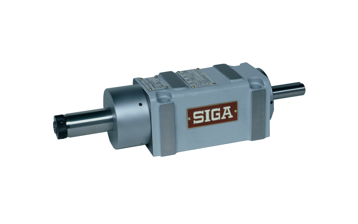
This is a high-speed, small-diameter drill spindle. The bearing configuration is the same as the 7F type. It is classified into L type, which uses an oil seal for the front seal, and H type, which uses a labyrinth seal. They are used based on the rotational speed and the presence of cutting oil. The shaft diameter is only φ20.
| Spindle Diameter | Motor Power | Case K Compatible | Case P Compatible |
| 20―60mm | 0.75―3.7KW | ー | 〇 |
Check 7D Details
| Model | Spindle Diameter | Usual Maximum Rotation Speed (rpm) |
Maximum Allowable Motor Power (KW) |
Used Bearings | Weight (Kgf) |
CAD Data |
|
| (mm) | MT # | ||||||
| 7D-20FH | 20 | 1 | 10,000 | 0.75 | Angular contact ball bearings |
9.7 | zip / lzh |
| 7D-20FH-P | 20 | 1 | 10,000 | 0.75 | 11 | zip / lzh | |
| 7D-20FL | 20 | 1 | 6,000 | 0.75 | 9.7 | zip / lzh | |
| 7D-20FL-P | 20 | 1 | 6,000 | 0.75 | 11 | zip / lzh | |
3D
3D-50
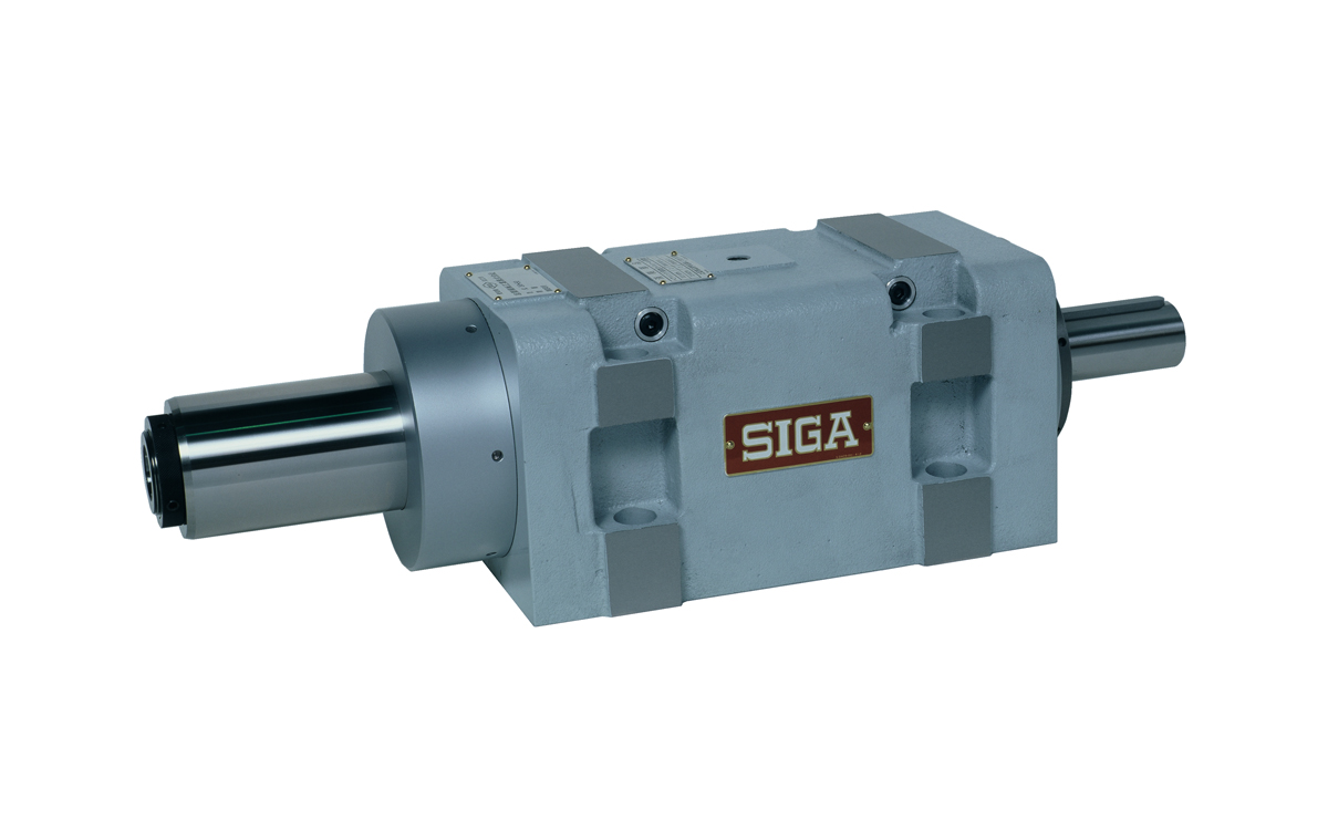
This is a spindle unit for large drill machining. The bearing configuration is the same as the 3R boring spindle, making it suitable for heavy loads. The shaft diameter lineup includes φ25, φ45, and φ50. There is also a special case available with support hole bosses for pilot bars used in the bushing-in method.
| Spindle Diameter | Motor Power | Case K Compatible | Case P Compatible |
| 20―60mm | 0.75―3.7KW | ー | 〇 |
Check 3D Details
| Model | Spindle Diameter | Usual Maximum Rotation Speed (rpm) |
Maximum Allowable Motor Power (KW) |
Used Bearings | Weight (Kgf) |
CAD Data |
|
| (mm) | MT # | ||||||
| 3D-25 | 25 | 1 | 3,500 | 0.75 | Tapered roller bearings + Angular contact ball bearings |
9.7 | zip / lzh |
| 3D-25-P | 25 | 1 | 3,500 | 0.75 | 11 | zip / lzh | |
| 3D-45 | 45 | 2,3,4 | 2,000 | 3.7 | 38.5 | zip / lzh | |
| 3D-45-K | 45 | 2,3,4 | 2,000 | 3.7 | 38.5 | zip / lzh | |
| 3D-45-P | 45 | 2,3,4 | 2,000 | 3.7 | 48.5 | zip / lzh | |
| 3D-50 | 50 | 3,4 | 1,500 | 3.7 | 70 | zip / lzh | |
| 3D-50-K | 50 | 3,4 | 1,500 | 3.7 | 70 | zip / lzh | |
| 3D-60 | 60 | 3,4 | 1,500 | 3.7 | 83 | zip / lzh | |
| 3D-60-K | 60 | 3,4 | 1,500 | 3.7 | 83 | zip / lzh | |

2D-20-P
This is a spindle unit for general drilling and reaming operations.
The shaft diameter lineup includes φ30 and φ45.
There is also a special case available with support hole bosses for pilot bars used in the bushing-in method.
| Spindle Diameter | Motor Power | Case K Compatible | Case P Compatible |
| 30―45mm | 1.2―2.3KW | ー | 〇 |
Check 2D Details
| Model | Spindle Diameter | Usual Maximum Rotation Speed (rpm) |
Maximum Allowable Motor Power (KW) |
Used Bearings | Weight (Kgf) |
CAD Data |
|
| (mm) | MT # | ||||||
| 2D-30 | 30 | 1,2 | 2,500 | 1.5 | Tapered roller bearings |
25 | zip / lzh |
| 2D-30-K | 30 | 1,2 | 2,500 | 1.5 | 25 | zip / lzh | |
| 2D-30-P | 30 | 1,2 | 2,500 | 1.5 | 33 | zip / lzh | |
| 2D-45 | 35 | 2,3 | 2,000 | 2.2 | 37 | zip / lzh | |
| 2D-45-K | 35 | 2,3 | 2,000 | 2.2 | 37 | zip / lzh | |
| 2D-45-P | 35 | 2,3 | 2,000 | 2.2 | 47 | zip / lzh | |
Injector
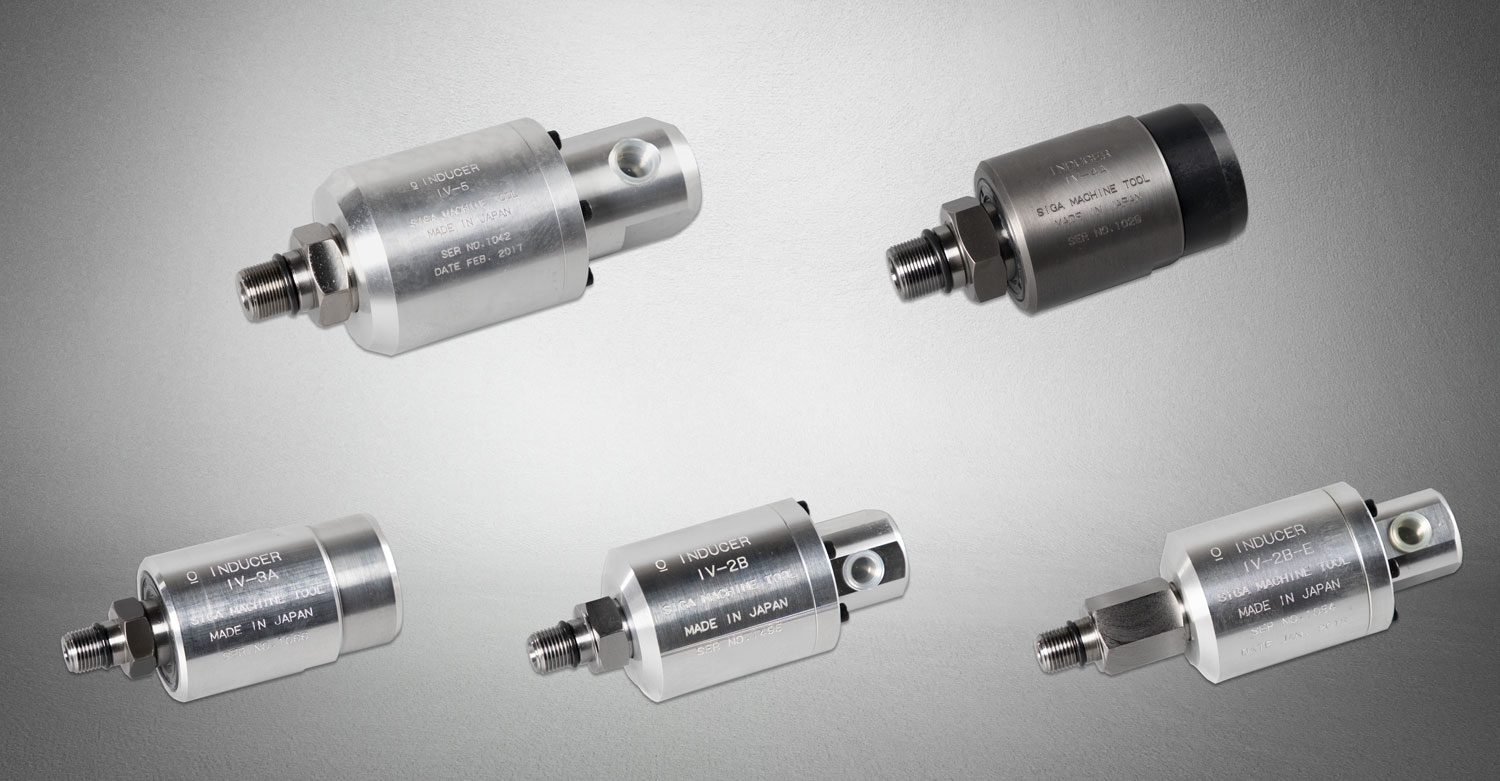
This is a rotary joint (rotary joint) that is essential for passing cutting oil through the shaft core.
It can be used with 4F type gundrill spindles as well as various boring spindles by using the G-type (injector mounting screw processing) (except for some models).
Check Injector Details
| Model | Maximum Allowable Rotation Speed RPM |
Maximum Allowable Pressure kfg/cm² |
Discharge Volume L/min |
Weight g |
Mounting Screw Diameter | CAD Data |
||
| IV-2B | 6000 | 65 | 80 | 840 | 左 5/8-18 UNF | zip | lzh | |
| IV-2B-E | 6000 | 65 | 80 | 950 | 左 5/8-18 UNF | zip | lzh | |
| IV-3A | 1000 | 2 | 50 | 1300 | 左 5/8-18 UNF | zip | lzh | |
| IV-4A | 800 | 2 | 100 | 2550 | 右M25P1.5 | zip | lzh | |
| IV-5 | 4000 | 60 | 200 | 3000 | 右M25P1.5 | zip | lzh | |
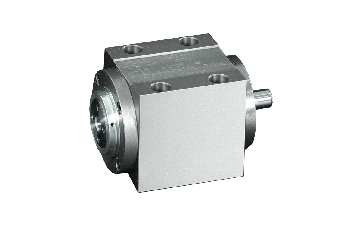
The S-CUBE is a revolutionary ultra-compact spindle that brings innovation to various industries. Despite its compact size of just 65mm square, it achieves an astonishing rotation speed of up to 20,000 RPM and high precision with only 2μm of runout. This spindle is powered by a dedicated motor providing a maximum speed of 300 RPM and a rated torque of 0.4N・m. The introduction of S-CUBE enables miniaturization of machines, and automates deburring tasks that were previously not feasible.
Check S-CUBE Details
Blueprint information here
| Model | Maximum RPM | Weight g |
CAD Data |
|
| CSU-17 (S-CUBE Cast) | 20,000 | 1900 | zip | |
| CSU-17-AL (S-CUBE Aluminum) | 20,000 | 900 |
Special Spindle
We can design and manufacture special spindles according to your specific requirements, starting from a single unit.
Examples include spring plunger type, built-in motor spindle, and other special applications or replacements. We can accommodate various requests with short lead times.
Please contact the Technical Department of SIGA Machinery Industry for more information.

Hydraulic Feed Unit
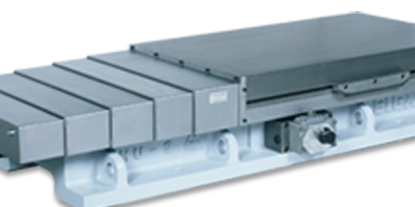
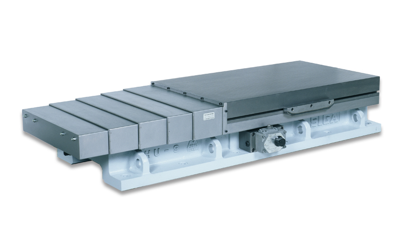
This is a double-acting hydraulic slide table primarily designed for heavy-duty cutting. The sliding surface of the table is coated with standard fluororesin (Takaito B), and the base sliding surface undergoes high-frequency induction hardening treatment, providing both high durability and excellent operability. A shut-off valve is included.
HU-4B
Check Hydraulic Feed Unit Details
| Model | Base Size Width × Length |
Table Size Width × Length |
Total Height | Cylinder Diameter × Stroke |
Maximum Load Capacity (kg) |
Weight (kg) |
CAD Data |
| HU- 12B-60×120 | 220×420 | 220×280 | 135 | φ60× 120 | 100 | 62 | zip / lzh |
| HU- 1B-60×120 | 220×420 | 220×410 | 135 | φ60× 120 | 200 | 70 | zip / lzh |
| HU- 1B-60×220 | 220×670 | 220×410 | 135 | φ60× 220 | 200 | 85 | zip / lzh |
| HU- 11B-60×120 | 300×560 | 300×410 | 205 | φ60× 120 | 450 | 155 | zip / lzh |
| HU- 1101B-60×120 | 250×560 | 250×410 | 205 | φ60× 120 | 350 | 125 | zip / lzh |
| HU- 1102B-60×120 | 360×560 | 360×410 | 205 | φ60× 120 | 450 | 175 | zip / lzh |
| HU- 2B-80×200 | 360×670 | 360×420 | 205 | φ80× 200 | 500 | 185 | zip / lzh |
| HU- 201B-60×200 | 250×670 | 250×420 | 205 | φ60× 200 | 400 | 150 | zip / lzh |
| HU- 202B-80×200 | 420×670 | 420×420 | 205 | φ80× 200 | 650 | 225 | zip / lzh |
| HU- 13B-80×250 | 360×800 | 360×525 | 205 | φ80× 250 | 600 | 230 | zip / lzh |
| HU- 13002B-80×350 | 360×800 | 360×420 | 205 | φ80× 350 | 500 | 220 | zip / lzh |
| HU- 1301B-60×230 | 250×800 | 250×550 | 205 | φ60× 230 | 500 | 185 | zip / lzh |
| HU- 1302B-80×250 | 420×800 | 420×525 | 205 | φ80× 250 | 800 | 285 | zip / lzh |
| HU- 13022B-80×350 | 420×800 | 420×420 | 205 | φ80× 350 | 650 | 265 | zip / lzh |
| HU- 3B-80×380 | 360×940 | 360×525 | 205 | φ80× 380 | 600 | 245 | zip / lzh |
| HU- 3002B-80×450 | 360×940 | 360×420 | 205 | φ80× 450 | 500 | 225 | zip / lzh |
| HU- 302B-80×380 | 420×940 | 420×525 | 205 | φ80× 380 | 800 | 310 | zip / lzh |
| HU- 3022B-80×450 | 420×940 | 420×420 | 205 | φ80× 450 | 650 | 280 | zip / lzh |
| HU- 4B-100×250 | 500×885 | 500×600 | 230 | φ100× 250 | 1,000 | 410 | zip / lzh |
| HU- 402B-100×250 | 500×885 | 600×600 | 230 | φ100× 250 | 1,000 | 430 | zip / lzh |
| HU- 4B-100×380 | 500×1000 | 500×600 | 230 | φ100× 380 | 1,000 | 450 | zip / lzh |
| HU- 402B-100×380 | 500×1000 | 600×600 | 230 | φ100× 380 | 1,000 | 470 | zip / lzh |
| HU- 4B-100×480 | 500×1100 | 500×600 | 230 | φ100× 480 | 1,000 | 470 | zip / lzh |
| HU- 402B-100×480 | 500×1100 | 600×600 | 230 | φ100× 480 | 1,000 | 490 | zip / lzh |
| HU- 4B-100×650 | 500×1300 | 500×600 | 230 | φ100× 650 | 1,000 | 545 | zip / lzh |
| HU- 402B-100×650 | 500×1300 | 600×600 | 230 | φ100× 650 | 1,000 | 565 | zip / lzh |
| HU- 5B-80×530 | 360×1200 | 360×650 | 205 | φ80× 530 | 650 | 330 | zip / lzh |
| HU- 5003B-80×650 | 360×1200 | 360×525 | 205 | φ80× 650 | 600 | 315 | zip / lzh |
| HU- 502B-80×530 | 420×1200 | 420×650 | 205 | φ80× 530 | 1,000 | 380 | zip / lzh |
| HU- 5023B-80×650 | 420×1200 | 420×525 | 205 | φ80× 650 | 800 | 360 | zip / lzh |
| HU- 6B-80×750 | 360×1550 | 360×700 | 220 | φ80× 750 | 700 | 450 | zip / lzh |
| HU- 9B-120×300 | 600×940 | 600×600 | 300 | φ120× 300 | 1,500 | 650 | zip / lzh |
| HU- 9B-120×500 | 600×1550 | 600×1000 | 300 | φ120× 500 | 2,000 | 1,060 | zip / lzh |
Pressure and Temperature Compensated Single-stage Shut-off Valve
Model HF-TGM
This shut-off valve is used to adjust the feed motion and speed of machine tools and other equipment. By the movement of the cam plunger, it changes the circuit to switch between rapid feed, cutting feed, and rapid return, and adjusts the cutting feed using the built-in flow control valve. It is equipped with pressure and temperature compensation, ensuring a constant controlled flow rate regardless of pressure fluctuations and viscosity changes due to temperature variations at the inlet and outlet.

| Model | Maximum Operating Pressure | Free Flow | Cam Push Force | Weight | Flow Adjustment Range |
| HF-TGM001-03 | 7.0Mpa | 30L/min | 120N | 3.5kg | 0.1-1 |
| HF-TGM002-03 | 0.1-2 | ||||
| HF-TGM004-03 | 0.2-4 |
kgf = N × 0.101972
Pressure Compensated Two-stage Shut-off Valve
Model HF-ZGMD
The two-stage shut-off valve is used to adjust the feed motion and speed of machine tools and other equipment in two stages. By the movement of the cam plunger, it changes the circuit to switch between rapid feed, cutting feed, micro feed, and rapid return, and adjusts the cutting feed and micro feed using the built-in flow control valve. It is equipped with pressure compensation, ensuring a constant controlled flow rate regardless of pressure fluctuations at the inlet and outlet.
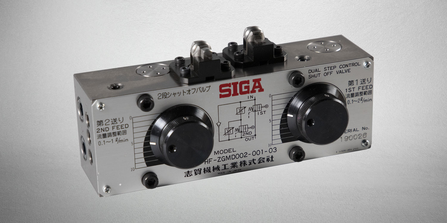
| Model | Maximum Operating Pressure | Free Flow | Cam Push Force | Weight | Flow Adjustment Range Stage 1 |
Flow Adjustment Range Stage 2 |
| HF-ZGMD002-001-03 | 7.0Mpa | 30L/min | 120N | 5.4kg | 0.1-2 | 0.1-1 |
| HF-ZGMD004-001-03 | 0.2-4 | 0.1-1 |
kgf = N × 0.101972
Pressure and Temperature Compensated Two-stage Shut-off Valve
Model HF-TGMD
The two-stage shut-off valve is used to adjust the feed motion and speed of machine tools and other equipment in two stages. By the movement of the cam plunger, it changes the circuit to switch between rapid feed, cutting feed, micro feed, and rapid return, and adjusts the cutting feed and micro feed using the built-in flow control valve. It is equipped with pressure and temperature compensation, ensuring a constant controlled flow rate regardless of pressure fluctuations and viscosity changes due to temperature variations at the inlet and outlet.
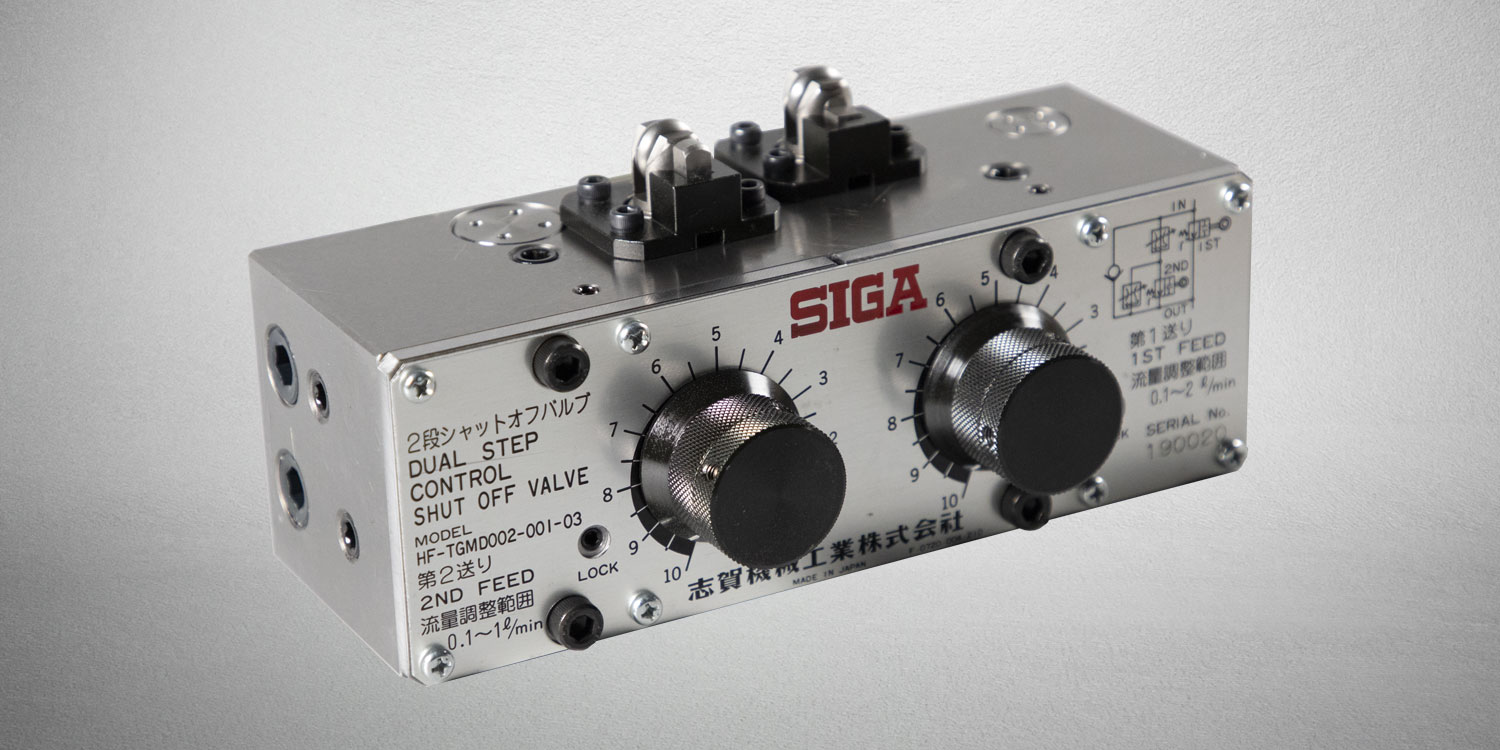
| Model | Maximum Operating Pressure | Free Flow | Cam Push Force | Weight | Flow Adjustment Range Stage 1 |
Flow Adjustment Range Stage 2 |
| HF-TGMD002-001-03 | 7.0Mpa | 30L/min | 120N | 6.5kg | 0.1-2 | 0.1-1 |
| HF-TGMD004-001-03 | 0.2-4 | 0.1-1 |
kgf = N × 0.101972
Mechanical Feed Unit
The mechanical feed unit is a slide table that utilizes a ball screw drive system and is compatible with NC control, while retaining the features of the hydraulic feed unit. The stroke may differ slightly from the hydraulic system.
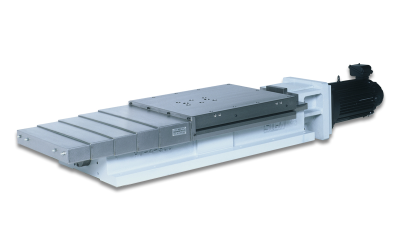
HU-4MT
Check Mechanical Feed Unit Details
| Model | Base Size (Width × Length) |
Table Size (Width × Length) |
Overall Height | Stroke | Basic Unit Model | CAD Data |
| HU- 1102M-90 | 360× 560 | 360× 410 | 205 | 90 | HU- 1102-120 | zip / lzh |
| HU- 2M-190 | 360× 670 | 360× 420 | 205 | 190 | HU- 2-200 | zip / lzh |
| HU- 202M-190 | 420× 670 | 420× 420 | 205 | 190 | HU- 202-200 | zip / lzh |
| HU- 13M-215 | 360× 800 | 360× 525 | 205 | 215 | HU- 13-250 | zip / lzh |
| HU- 1302M-215 | 420× 800 | 420× 525 | 205 | 215 | HU- 1302-250 | zip / lzh |
| HU- 13002M-320 | 360× 800 | 360 × 420 | 205 | 320 | HU- 13002-350 | zip / lzh |
| HU- 13022M-320 | 420× 800 | 420× 420 | 205 | 320 | HU- 13022-350 | zip / lzh |
| HU- 3M-355 | 360× 940 | 360× 525 | 205 | 355 | HU- 3-380 | zip / lzh |
| HU- 302M-355 | 420× 940 | 420× 525 | 205 | 355 | HU- 302-380 | zip / lzh |
| HU- 3002M-460 | 360× 940 | 360× 420 | 205 | 460 | HU- 3002-450 | zip / lzh |
| HU- 3022M-460 | 420× 940 | 420× 420 | 205 | 460 | HU- 3022-450 | zip / lzh |
| HU- 4M-225 | 500× 885 | 500× 600 | 230 | 225 | HU- 4-250 | zip / lzh |
| HU- 402M-225 | 500× 885 | 600× 600 | 230 | 225 | HU- 402-250 | zip / lzh |
| HU- 4M-340 | 500× 1000 | 500× 600 | 230 | 340 | HU- 4-380 | zip / lzh |
| HU- 402M-340 | 500× 1000 | 600× 600 | 230 | 340 | HU- 402-380 | zip / lzh |
| HU- 4M-440 | 500× 1100 | 500× 600 | 230 | 440 | HU- 4-480 | zip / lzh |
| HU- 402M-440 | 500× 1100 | 600× 600 | 230 | 440 | HU- 402-480 | zip / lzh |
| HU- 4M-640 | 500× 1300 | 500× 600 | 230 | 640 | HU- 4-650 | zip / lzh |
| HU- 402M-640 | 500× 1300 | 600× 600 | 230 | 640 | HU- 402-650 | zip / lzh |
| HU- 5M-490 | 360× 1200 | 360× 650 | 205 | 490 | HU- 5-530 | zip / lzh |
| HU- 502M-490 | 420× 1200 | 420× 650 | 205 | 490 | HU- 502-530 | zip / lzh |
| HU- 5003M-615 | 360× 1200 | 360× 525 | 205 | 615 | HU- 5003-650 | zip / lzh |
| HU- 5023M-615 | 420× 1200 | 420× 525 | 205 | 615 | HU- 5023-650 | zip / lzh |
| HU- 6M-790 | 360× 1550 | 360× 700 | 220 | 790 | HU- 6-750 | zip / lzh |
| HU- 9M-280 | 600× 940 | 600× 600 | 300 | 280 | HU- 9-300 | zip / lzh |
| HU- 9M-490 | 600× 1550 | 600× 1000 | 300 | 490 | HU- 9-500 | zip / lzh |
Index Table
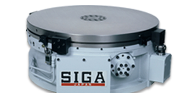
This is a large index table developed for rotary indexing machines. It boasts high durability and a large load capacity with a hydraulic-driven rack and ratchet mechanism. It ensures reliable operation with two overrun prevention cylinders.
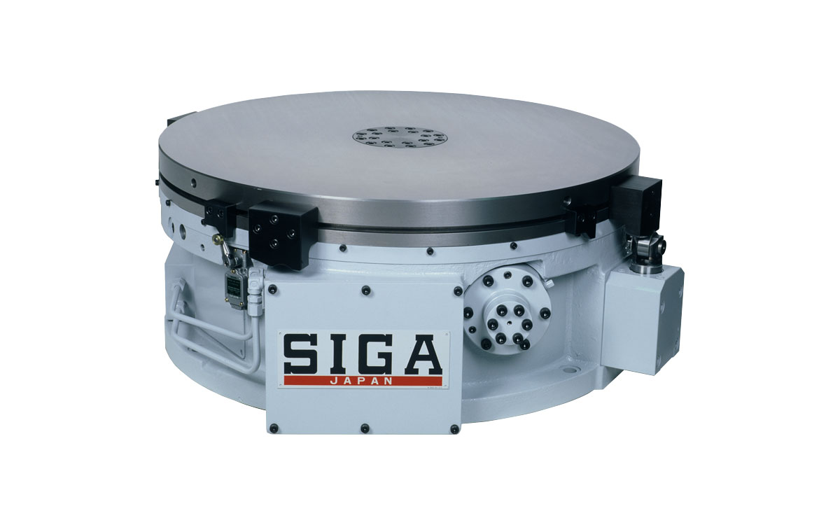
Check Index Table Details
| Model | RT8D | RT10D | RT12D |
| Permissible Load | 7840N | 14700N | 19600N |
| Permissible Lateral Load | 4900N | 5880N | |
| (Force towards the center at a position 100mm above the table surface) | |||
| Drive Method | Hydraulic-driven rack and ratchet mechanism | ||
| Division Method, Equal Division | Tapered pin insertion method: 4, 5, 6, 7, 8, 9, 10, 11, 12 equal divisions | ||
| Indexing Time | 5 seconds/6 equal divisions | 6 seconds/6 equal divisions | |
| Pin withdrawal - Table unclamp - Table rotation - Pin insertion - Table clamp | |||
| Table Clamp | Available (No confirmation limit switch) | ||
| Hydraulic Operating Pressure | 2.0 ~ 2.5 MPa (max 3.0MPa) | ||
| Lubricating Oil Method | 200~300cc/8H at 0.5MPa or higher | 300~500cc/8H at 0.5MPa or higher | |
| Internal oil tank with built-in pump; centralized lubrication from external source is required for replenishment | |||
| Table Division Accuracy | ±0.02mm (±12sec) | ±0.025mm (±12sec) | ±0.03mm (±12sec) |
| Table Rotation Flatness | 0.02mm | 0.03mm | |
| Table Top Mounting Holes | Maximum additional machining hole diameter on the table top: 25mm (35mm at the thinnest section of the table top) | ||
| Weight | 850kg | 1100kg | 1700kg |
Splash Gun
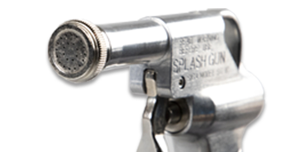
The Splash Gun is a coolant gun that is compatible with both water-soluble and oil-based coolants. It is designed with a nozzle that effectively flushes away chips with minimal flow rate. It is known for its ergonomic grip and durability, making it a hidden bestseller among SIGA products.

| Type | SG-1C |
| Weight | 480g |
| Pressure Resistance | 0.3MPa |
| Nozzle Diameter | φ1.4mm × 18 nozzles |

